Networking

Networking is the form of computer communication generally used for exchanging data and information. Two or more computers are connected together or networked by some types of communication media (wire or cable) to form a data path as to exchange program and data files between them.
Networking allows accessing shared output devices and data storage connected to the network. Examples of shard devices are printers, plotters and hard disks.

Need
Networking satisfies a broad range of purposes and meets various requirements. Networking has become essential for the following reasons:
1. File sharing
2. Resource sharing
3. Unlike equipment and communication.
4. To improve speed and accuracy.
5. Low cost.
6. For instant availability of data.
File Sharing
Networking enables a user to share files between all the connected computers. For example, the users of an organization having its different offices at distant places in a city, which are physically separated but are connected on a network, can share their files and data without moving physically to each and every office.
Resource Sharing
Laser printers and hard disks can be expensive. Networking enables users to share such resources by networking several computers together. For example, a company with say 20 users, each requiring only limited hard disk space and occasional printing, might save money by purchasing fewer resources and sharing them.
Unlike Equipment Communication
Through networking it is also possible to share and send messages between computers having equipment of different brands and using different operating systems like DOS, UNIX, MacOS, etc.
Improve Speed and Accuracy
Sending messages through a network is instantaneous as compared to a common letter, which takes several days to deliver. Computers can send data at very fast speed through satellite or microwave links. Also there are less chances of data being lost in case of networking. Accuracy is also maintained here.
Low Cost.
The cost of ttransferring data between computers connected on a network is lower than by other conventional means of transferring documents.
Instant Availability
Since the time taken in transferring data is quite small, data is available instantlyy at the other end. This feature is useful for communication price fluctuations in foreign exchange and in share/equity trading etc.

Terminology of Boolean Expressions

A Boolean expression has the following terms

Literals
A literal is a single Boolean variable or it's complement
Constant
A constant is a value or the quantity which has a fixed (unchanging) value. In real number (conventional) algebra, constants include all integers and fractions. In Boolean Algebra, there are only two possible constants 1 and 0. These two constants are used to describe true and false, YES or NO, etc.
Variable
A variable is a quantity which can change its value by taking on the value of any constant. At any one itme the variable has only one particular value of constant. There are only two values of constants in the Boolean System. Therefore, a variable in Boolean algebra can only be either 0 or 1. Variables are denoted by letters.
Term
A term is a literal or a collection of literals.
Product Term
A product ( logical AND) of several different literals is called the product term. For example :
A.B' is a product term
Sum Term
The Logical OR of Literals is called the sum term. For example:
A+B'+C
is an example of sum term
Sum of Products
It is the sum (logical OR) of product terms. For example 
A.B' +B.C + A.B.C
is the sum of three different erms i.e. A.B', B.C and A.B.C
Product of Sum
It is tthe product (logical AND) of sum terms. For example:
(A+B).(A+B'+C).(A+C)
is the product of three different sum terms i.e. (A+B), (A+B'+C) and (A+C)
Minterm
A minterm is an AND function that includes each variable once in its normal or complemented form. This is also known as the standard sum of products. For example:
If you have two variables, A and B, there are eight possible terms:
A, B, A', B', A'B', A'B, AB' and AB.
Similarly for three variables we have 26 possible terms.
Maxterm
A maxterm is a logical OR function that includes each variable once in its normal or complemented form. This is known as standard product of sums.

Basic Logic Gates

A logic gate is a simple electronic circuit, which operates on one or more input signals to produce standard output signals. Logic gates are the basic building blocks of all the electronic circuits in a computer. All circuits in a computer are made by the combination of logic gates. Every operation within a computer is carried out by signals passing through these logic gates. A few gates are discussed below:

There are seven basic logic gates: AND, OR, XOR, NOT, NAND, NOR, and XNOR.

The basic operations are described below with the aid of truth tables.

AND gate


The AND gate is an electronic circuit that gives a high output (1) only if all its inputs are high. A dot (.) is used to show the AND operation i.e. A.B. Bear in mind that this dot is sometimes omitted i.e. AB
 
OR gate


The OR gate is an electronic circuit that gives a high output (1) if one or more of its inputs are high.  A plus (+) is used to show the OR operation.

 
The NOT gate is an electronic circuit that produces an inverted version of the input at its output.  It is also known as an inverter.  If the input variable is A, the inverted output is known as NOT A.  This is also shown as A', or A with a bar over the top, as shown at the outputs. The diagrams below show two ways that the NAND logic gate can be configured to produce a NOT gate. It can also be done using NOR logic gates in the same way.

 
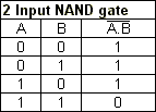
This is a NOT-AND gate which is equal to an AND gate followed by a NOT gate.  The outputs of all NAND gates are high if any of the inputs are low. The symbol is an AND gate with a small circle on the output. The small circle represents inversion.

NOR gate


This is a NOT-OR gate which is equal to an OR gate followed by a NOT gate. The outputs of all NOR gates are low if any of the inputs are high.
The symbol is an OR gate with a small circle on the output. The small circle represents inversion.

EXOR gate


The 'Exclusive-OR' gate is a circuit which will give a high output if either, but not both, of its two inputs are high. An encircled plus sign () is used to show the EOR operation.

EXNOR gate


The 'Exclusive-NOR' gate circuit does the opposite to the EOR gate. It will give a low output if either, but not both, of its two inputs are high. The symbol is an EXOR gate with a small circle on the output. The small circle represents inversion.


The NAND and NOR gates are called universal functions since with either one the AND and OR functions and NOT can be generated.

Note:

A function in sum of products form can be implemented using NAND gates by replacing all AND and OR gates by NAND gates.
A function in product of sums form can be implemented using NOR gates by replacing all AND and OR gates by NOR gates.

Logical Operators : AND Operator

This operator is also known as the logical multiplication operator and is represented by the dot (.) symbol. The AND operation is used between the variables a, b in the manner a AND b. The output in this case is 1 only when both a and b are 1. And if both are 0 or if any one of them is 0, then he output is also 0. The rules of the AND operation are:

0 . 0 = 0
0 . 1 = 0
1 . 0 = 0
1 . 1 = 1

The Truth table is shown below
Through a Venn diagram and AND operation would be shown in the figure below:

Logical Operators : OR Operator

OR is the logical addition operator and is denoted by the plus (+) symbol. Suppose there are two variables a and b; since each variable can have values of either 1 or 0 a total of four combinations of inputs are possible. An OR operation shows the output as 1 or HIGH when either of the inputs is 1 or HIGH, and also when both of the inputs are 1. So a OR b can be shown through a truth table as follows:
Here we say
0 + 0 = 0
0 + 1 = 1
1 + 0 = 1
1 + 1 = 1

Here 1 + 1 = 1. That is why the OR operator is different from the normal addition operator
The OR operation can be shown through a Venn diagram as shown in the figure below:


Logical Operators : NOT Operator

In boolean algebra any variable can have either of the two values, 0 or 1. And in terms of digital circuits it can be either of two values, LOW or HIGH. Like 0 and 1, LOW and HIGH are complements of each other. The NOT operator can be used to provide the complements of values (0,1 ; LOW, HIGH). It is a unary operator. It operates on single variable. It can be written as a bar above a variable ā or by the symbol such as a'. If a' is 1, then a= 0. Complementation or the NOT operation can be understood easily through Venn diagram.

In this diagram the circle represents a and the shaded portion of the rectangle represents ā , i.e, the complement of a.
If a=1 then ā = 0,
If a = True then ā = False.
The truth table for the NOT operator is
a            ā
0                  1
1                  0